


 Français
 Русский
 Español
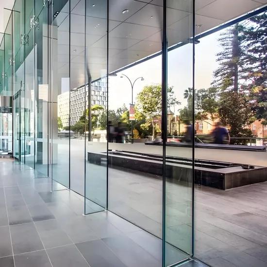
A sound structural glass fin design turns vertical glass into a load-bearing member: the fin stands perpendicular to the facade, carries panel wind load and transfers it to the main structure without aluminium mullions. Sizing and connecting it correctly prevents leaks, rattles and inspection failures.
Glass fins define a fin-supported point-supported curtain wall, alongside spider and cable-braced options. Our glass fin vs spider system comparison weighs aesthetics, spans and cost; the background starts with point-fixed glass curtain walls.
What a Glass Fin Does in a Point-Supported Facade
In a fin-supported facade, panels face outwards while fins run vertically behind or between them, normal to the glass like transparent mullions. Wind pressure pushes on a panel, force reaches its edge fixings, and the fin carries the resulting bending load down to the slab or head beam. Being glass itself, the fin adds almost no visual line, suiting entrance halls, atria and flagship retail.
Three load actions are sized independently: the fin resists wind bending, its base resists the resulting moment and shear, and panel-to-fin fixings transfer load without punching through glass. Under-designing any one undermines the whole facade.
Sizing the Fin: Span, Wind Load and Glass Configuration
Fin dimensions are never chosen from a generic catalogue table. Height follows the storey or span; depth (the projection from the facade plane) and thickness grow with wind pressure, fin spacing, panel size and fixing pattern. The section is fixed by the engineer’s calculation using supplier glass data — no fixed thickness or section belongs in a tender without it.
Several factors feed the sizing:
- Wind pressure and height above ground, which drive bending demand on the fin.
- Fin spacing and panel bay size, which set the tributary area each fin carries.
- Glass configuration: monolithic toughened where the fin is drilled; toughened-laminated for higher loads, long spans or spliced multi-storey fins; laminated for fracture retention.
- Splice conditions: fins too tall for one toughening unit are joined end-to-end on steel splice plates, engineered rather than improvised.
- Fabrication limits, such as toughening-furnace aspect-ratio constraints, which can govern a very tall, thin fin.
Annealed, toughened and laminated glass bend differently, so the engineer selects the make-up before finalising dimensions; thickness and depth are calculation outputs, not copied from another project.
Connections to the Main Structure: Base, Top and Ends
The base anchors the fin to the slab or curb through a fin base shoe or channel gripping the lower edge, bolted to an anchor in concrete or steel; the shoe spreads the moment and shear so glass never bears directly on metal. Anchor type — cast-in channel, chemical or expansion bolt — follows the substrate; edge distances come from the supplier’s data, not guesswork.
The top provides lateral restraint, not a rigid lock, allowing controlled movement that absorbs thermal expansion and sway; a fin locked rigidly at both ends can crack under temperature change. Over one storey, end splices join sections on clamped steel plates aligned to the centre plane; an offset splice introduces eccentric loading the glass was not designed for.
Building a fin-supported facade? Browse our point-supported systems hardware for base shoes, fin clamps and spiders sized within your engineer’s envelope.
Connecting Facade Panels to the Fin
Panels meet the fin through one of three connection families, often combined on site:
- Fin clamps and edge clips grip the panel edge alongside the fin, usually with isolation gaskets, for panels fixed continuously along an edge.
- Spider fittings and rosettes pass through drilled holes and reach back to the fin, carrying load at discrete points; arm spacing, hole size and rated capacity come from the manufacturer’s data. Our spider fitting dimensions and load capacity guide covers sizing basics.
- Structural silicone bonding adheres the panel to a fin or bracket without drilling, used where a visible fixing would compromise the design; bead size and bond length follow the supplier’s specification.
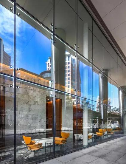
Every connection keeps metal off the glass: EPDM gaskets, isolation pads and setting blocks sit between stainless steel and glass. Over-torquing a clamp or spider concentrates stress and can start a crack; under-torquing lets the panel move under wind. Torque values come from the supplier, not feel on site.
Tolerances, Alignment and Installation
Structures move and glass is precise, so fixings must absorb the difference. Set fin centre lines against the structural grid before base shoes are fixed; establish plumb with a laser, because a leaning fin pulls every connected panel out of line. Leave the movement gap at the head and splices, and protect edges with setting blocks so glass never bears on a shoe or curb.
Stainless grade follows the environment: 304 inland, 316 for coastal, poolside or aggressive locations, confirmed with the supplier. Apply final torque only after the run is aligned and re-checked, not fixing by fixing.
Common Design Mistakes to Avoid
- Sizing the fin from a generic catalogue section instead of a project-specific wind calculation.
- Locking the fin rigidly at both ends with no movement allowance, inviting thermal stress cracking.
- Letting metal bear on glass at the shoe or clamps without gaskets or isolation pads.
- Drilling a fin or panel without toughened glass suited to point fixings.
- Setting a splice plate off the fin centre plane, creating eccentric load.
- Estimating torque and anchor edge distances instead of using supplier data.
- Specifying 304 hardware for a coastal site without upgrading to 316.
When to Bring in a Structural Engineer
A structural glass fin design should go to a qualified engineer whenever the facade exceeds one storey, faces high wind or an exposed location, carries large panels, uses spliced fins, or sits over occupied space below. The engineer confirms section, base moment, fixing pattern and splice detail; the supplier then selects shoes, clamps and spiders within it. Treating the fin as a glazing detail rather than structure causes most failed projects.
Structural Glass Fin Design FAQ
How is the glass fin thickness determined? From the engineer’s bending calculation against wind pressure, span and fin spacing, using glass supplier data; never take it from a general table or copy another building.
What glass types are used for fins? Monolithic toughened where holes are drilled; toughened-laminated for higher loads, long spans or spliced multi-storey fins; laminated where fracture retention matters. The choice follows the load case.
How are facade panels fixed to a glass fin? Through fin edge clamps, spider fittings at drilled points, or structural silicone bonding; method, gasket detail and capacity come from the supplier’s data.
Does a fin need fixing at the top? The top gives lateral restraint with controlled movement, not a rigid lock, allowing thermal expansion and sway; the base shoe carries the main moment and shear.
Can one fin span two storeys? Often not as one piece; tall fins are spliced end-to-end on steel plates, engineered for continuous bending transfer and centred on the fin plane.
Which stainless grade should the connections use? 304 inland, 316 for coastal or aggressive environments; confirm the grade with the supplier against site exposure before ordering.
Planning a fin-supported facade? Send us the elevations and load brief, and Trilonum will assemble a base shoe, clamp and spider schedule within your engineer’s envelope — get a quotation from Trilonum.
